For this Comp Fab assignment, I had to design three different designs using code that utilize the three main methods of laser cutting; Laser engraving/etching, vector line marks and the standard laser cut. Etching moves the laser across a designated area at fast speeds to leave a burned mark, but not much depth. laser vector lines leave an indent, but do not cut all the way through. A laser cut separates the material fully.
All laser cuts were done at the CU Boulder BTU lab. The material used was cardboard form an electronics box
The code uses the same setup and external functions to save the plots, so only the draw function and any custom functions will be shown. The saving code can easily be changed to saving to a PDF format instead if the two mentions of SVG are changed to PDF.
import Turtle.*;
Turtle t;
import processing.pdf.*;
import processing.svg.*;
String fileName;
//global variables
color cut = color(255,0,0);//use stroke(X); to change the color of the lines
color etch = color(0,0,0);
color line = color(0,0,255);
void setup() {
size(500,500);
background(255);
stroke(0);
fill(etch);
t = new Turtle(this);
noLoop();//only use draw once
}
//saving the drawing
void keyPressed()
{
//press the 's' key to save a pdf of your drawing
if (key == 's')
{
//name of file is "turtleDrawing" plus a unique(ish) number
fileName= "turtleDrawing"+ second() +".svg";
beginRecord(SVG, fileName);
draw();
endRecord();
}
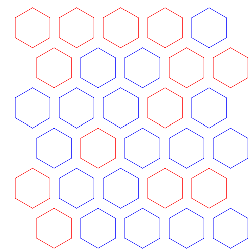
} Design 1: Hex Pattern
For this pattern, I wanted a pattern of randomly changing hexagonal holes; some empty, some full. Like a beehive populated by some bees. The system creates a hexagon at a set interval where on even layers, the even layer hexagons are offset by the radius.
void draw () {
  stroke(line);
  hex_grid(30.0,75.0,6,5,40,20);
}

void hex_grid(float x, float y, int rows, int columns, int size, int spacing)
{
  for(int i = 0; i < rows; i++)
  {
     for(int j = 0; j < columns; j++)
     {
       //color selection
       int rand = (int)random(0,2);
       switch(rand)
       {
         case 0://will laser cut a hex hole
           stroke(line);
           break;
         case 1://will just be a weak cut
           stroke(cut);
           break;
       }

       //drawing code
        float _x = j * (size * 1.7 + spacing) + x;
        float _y = i * (size * 1.5 + spacing) + y;
        if(i % 2 == 1)//if odd row...
        {
          _x += (1.65 * size) / 2 + (spacing * .5);
        }
        turtle_walk(_x, _y, size, 6);
     }
  }
}
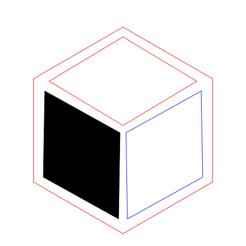
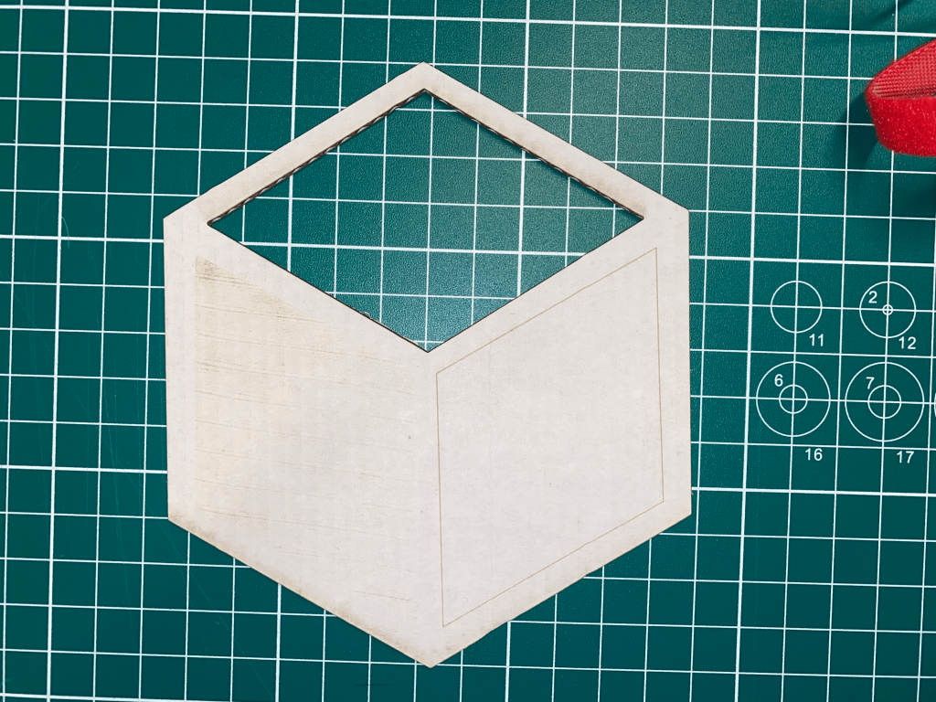
Design 2: Demo Cube
This design was made to demonstrate the three methods of using the laser. each “face” of the cube was done with a different method. As can be seen, the raster etch was very shallow. I later found out this was because the laser power setting had been tampered with. The rhombuses are also not correctly aligned. I couldn’t use the rotate function in processing because of the noLoop in the setup.
void draw () {
  float x = 100.0;
  float y = 100.0;
  float offset_x = 28;
  float offset_y = 50;
  float size_x = 50;
  float size_y = 30;

  //cut part
  stroke(cut);
  noFill();
  rhombus(x,y,size_x,size_y,0);

  //vector line part
  stroke(line);
  noFill();
  rhombus(x+offset_x,y+offset_y,size_x,size_y,2*PI/3);

  //etch
  stroke(etch);
  fill(etch);
  rhombus(x-offset_x,y+offset_y,size_x,size_y,PI/3);

  //outline cut
  stroke(cut);
  noFill();
  t.setX(x);
  t.setY(y-size_y - 7.5);
  t.setHeading(60.0);
  for(int i = 0; i < 6; i++)
  {

    t.right(60.0);
    t.forward(70.0);
  }
}

void rhombus(float x, float y, float size_x, float size_y, float rad)
{
  //println("new rhombus");
  float xs[] = {0,0,0,0};
  float ys[] = {0,0,0,0};
  for(int i = 0; i < 4; i++)
  {
    float selector = 1;
    float _x = x;
    float _y = y;
    if((i/2) % 2== 0)//if second half
      selector = -1 * selector;

    if(i % 2 == 0)//top points
    {
      _y += size_y * selector * sin(rad+PI/2);
      _x += size_y * selector * cos(rad+PI/2);
    }
    else//x points
    {
      _x += size_x * selector * cos(rad);
      _y += size_x * selector * sin(rad);
    }

    xs[i] = _x;
    ys[i] = _y;
    println(_x, " " ,_y);
  }
  //println(xs);
  //println(ys);
  quad(xs[0], ys[0], xs[1], ys[1], xs[2], ys[2], xs[3], ys[3]);
}
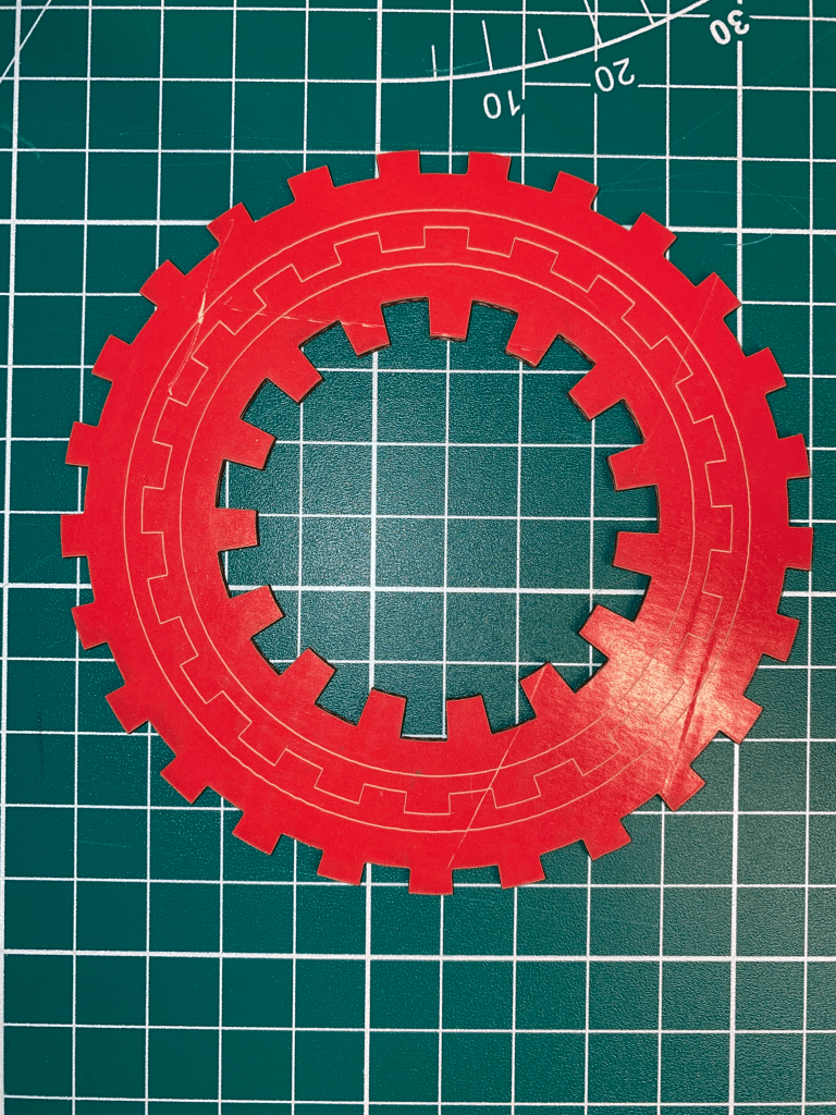
Design 3: Gears
I wanted to make a gear system that was modular with both size and teeth count. The system utilizes arcs and creating a lines between the two radai of the gear.
void draw () {
  noFill();
  stroke(line);
  circle(250,250,310);
  circle(250,250,255);
  gear(250.0,250.0, 272.5,20,20);

  stroke(cut);
  gear(250.0,250.0, 350.0,25,25);
  gear(250,250,180,15,40);
}

void gear(float x, float y, float diameter, float teeth_num, float teeth_length)
{
  float angle = 2*PI / (2 * teeth_num);
  for(float i = 0.0; i < (2*PI); i+= angle*2)
  {
    float ang1 = i;
    float ang2 = i + angle;
    float ang3 = ang2+ angle;
    //teeth bump
    arc(x,y,diameter+teeth_length,diameter+teeth_length,ang1, ang2);
    line(x+(diameter+teeth_length)*cos(ang1)/2, y+(diameter+teeth_length)*sin(ang1)/2,x+(diameter)*cos(ang1)/2, y+(diameter)*sin(ang1)/2);

    //teeth groove
    arc(x,y,diameter,diameter,ang2, ang2+angle);
    line(x+(diameter+teeth_length)*cos(ang2)/2, y+(diameter+teeth_length)*sin(ang2)/2,x+(diameter)*cos(ang2)/2, y+(diameter)*sin(ang2)/2);
  }
}
Conclusion
Lasers are an amazing technology that can create amazing 2D geometries. The main restriction with using a laser is both the Kerf and that lasers operate on a 2D plane. To create more interesting geometries with a laser in the future, multiple cuts will have to be used and the end products will have to be stacked to form a 3 dimensional object.

Leave a comment