A common use of fabrication techniques is to turn a modeled 3D object file into something existing in physical space. This task of making a 3D file readable for the manufacturing process is known as “slicing” a model. This Post will go over the process of creating a parametric 3D model and then slicing it through a custom slicer, both being created within the Rhino 8 platform.
The direct code can be referenced on my GitHub page. The files are simple grasshopper command files for Rhino 8, please note that the files will fail in any older version of Rhino.
Task 1: Parametric 3D Design
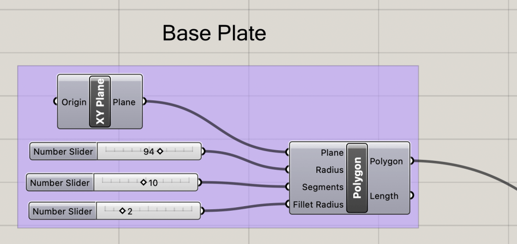
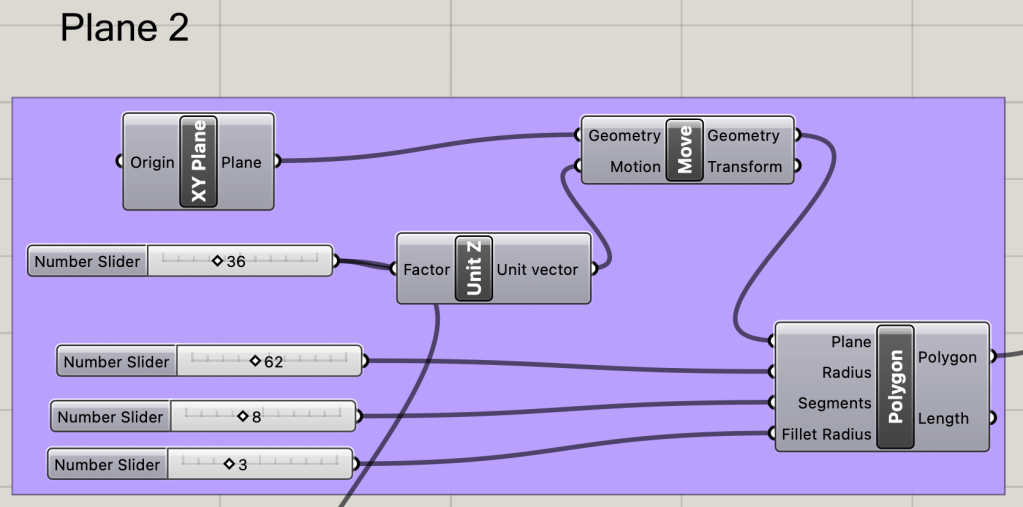
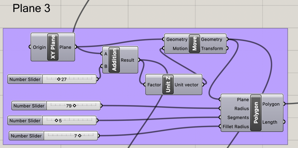
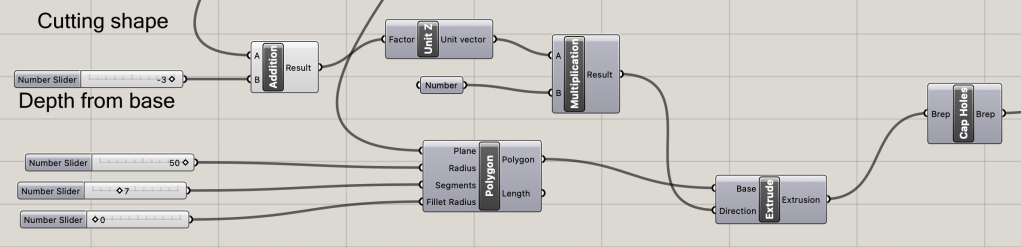
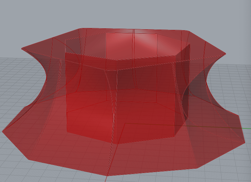
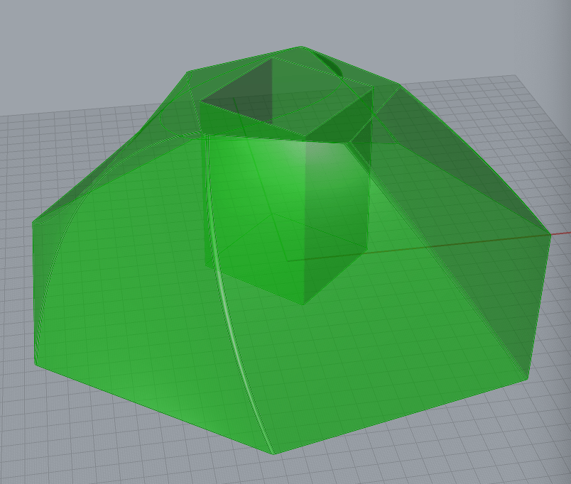
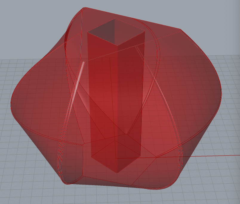
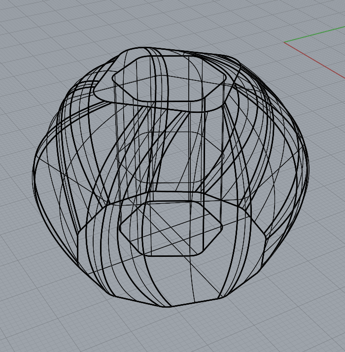
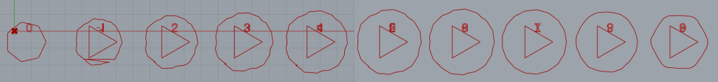
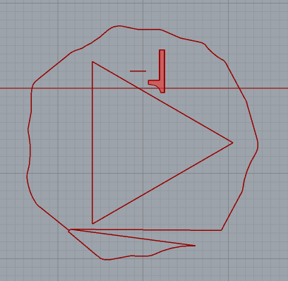
The geometries for this post will be created from the “L2_custom_geometry” grasshopper file on the GitHub page. The outside shape is variable with an hole to contain whatever is desired inside. The outisde is the loft produce of three of these variable shapes above one another, while the inside is a removal extrusion with a variable depth away from the bottom of the object.
Each shape is aligned with the X-Y Plane, created as a polygon with a variable amount of sides that can be rounded if desired. The radius is also variable with another slider. The later planes will directly scale with the height of the previous, so there is no errors created if the middle section gets above the top section.
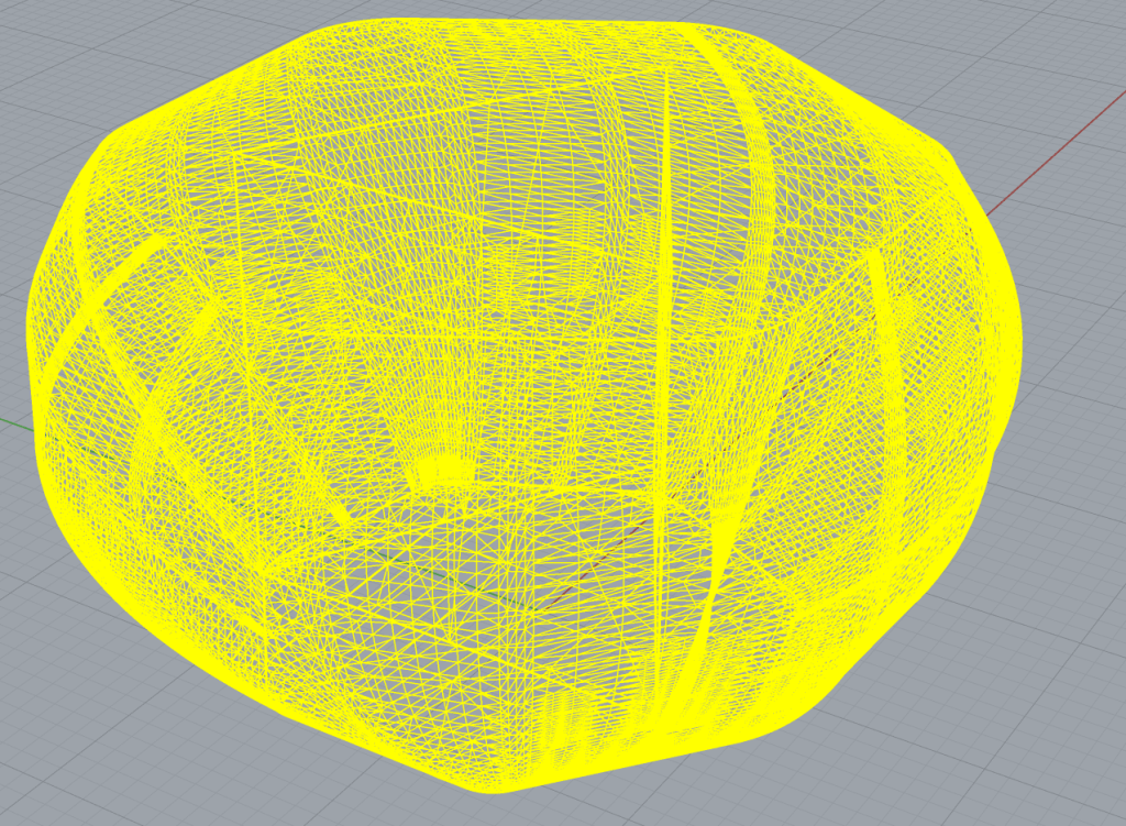
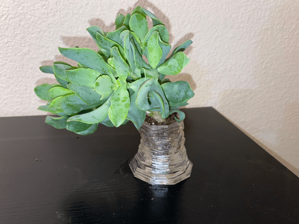
Some of the Generated Designs
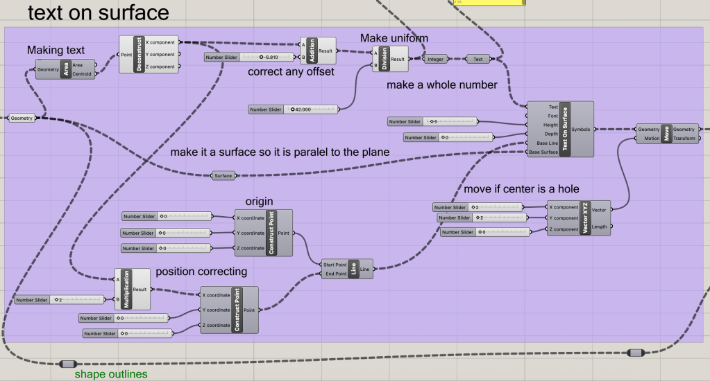
Task 2: Laser Slicer
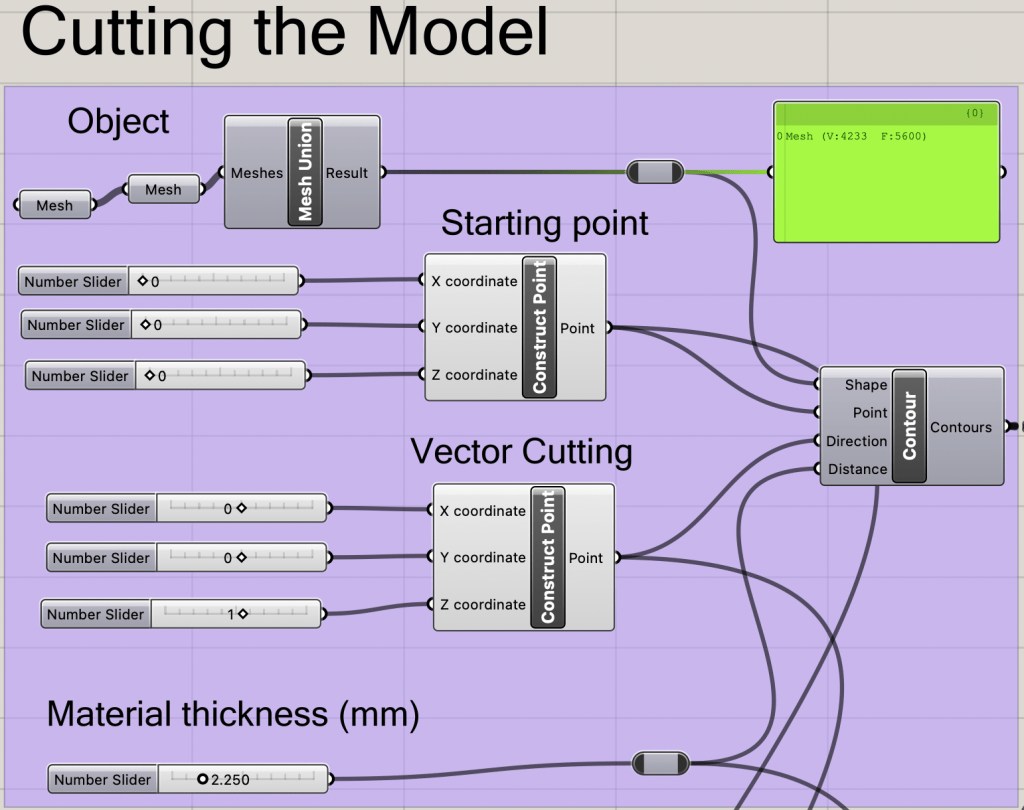
After the 3D object is generated, the model can be sliced using the “laser_slicer2” grasshopper file on the GitHub page. The laser slicer is divided into 4 main sections: generating the slices, filtering the slices, ordering slices flat and in order, creating the number order. There are also auxilery nodes attached from previous itterations that are not important to the main scope of this Laser slicer or project.
Generating the Slices
The contour Node will create slices perpendicular to the vector, starting on the starting point provided. The material thickness will determine the distance between slices.
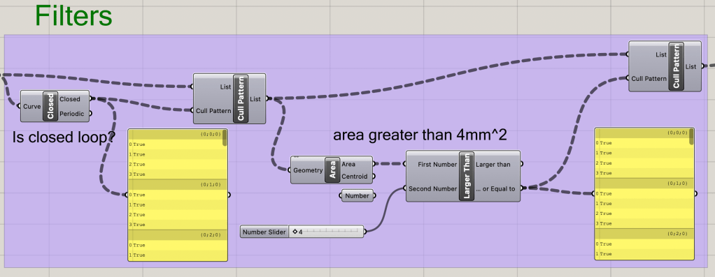
Filtering the Slices
There are two filters utilized in this laser slicer. First the slices from the contour are inspected for being complete loops. Any incomplete loops are removed from the queue. A minimum area of the slices is set and any slices below that threshold are also removed.
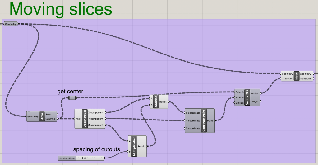
Ordering Slices Flat and in Order
Now that all of the slices are acceptable to be sliced by the lasers, they can be aligned and ordered along the X-axis. The easiest method of moving slices the correct distance is via measuring the distance the centroid of each slice is from the origin point. A secondary scaling factor is added as needed for larger slices. a transform vector is then created moving the slice from suspended space to the translated spot on the X-axis.
Creating the Number Order
As can be seen by all of the nodes, adding text to the slices is the most complicated and intensive part. Each slice will be referenced as a surface for the text to be placed upon. The new placement on the X-axis will be scaled down to become a whole number that is transformed into a marking number that can then become text on each slice. There is a slider for setign text size. A transofromation section for moving the text is incorporated if the center slice will be a hole. Something that should be noted of the base line input of the TextOnSurface Node, is that the text will be placed on the center of the line provided, so the line from the origin to the centroid of the slice has to be doubled to place the text in the desired area.
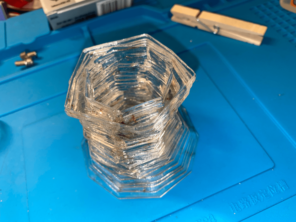
The Finished Result
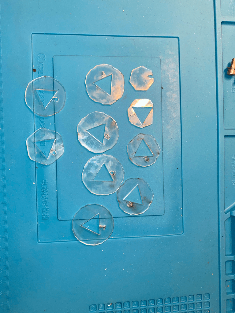
Task 3: Fabrication
As with all of the laser cutting fabrication parts, The machines were used at the CU ATLAS BTU Lab.
Organized Slices
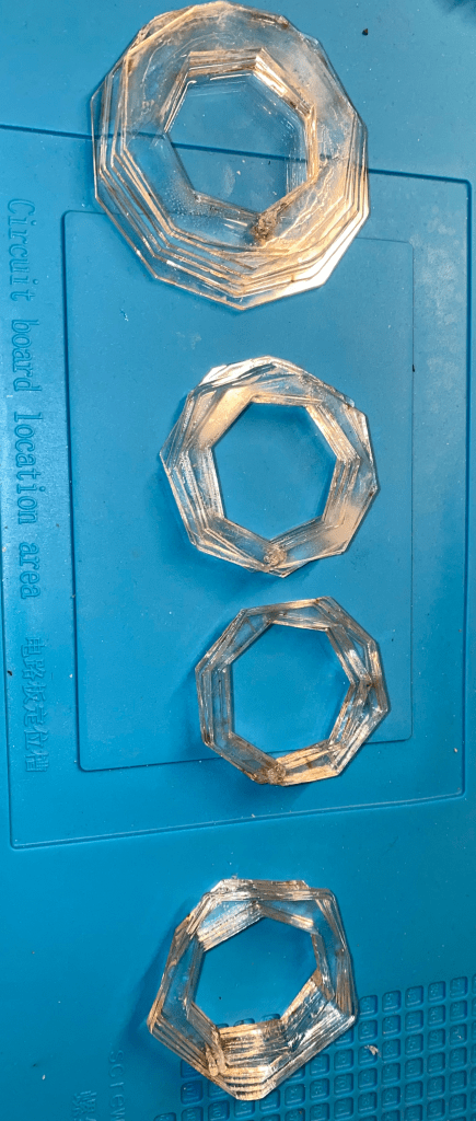
Assemblies
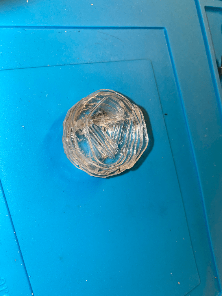
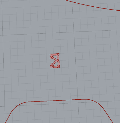
Known Errors
With some numbers in select spaces, the numbers will not overlap and instead flip over each other. The attached pictures are of a 2 slice being flipped and overlayed on itself. This had to be fixed in post processing before slicing. This issue most likely arises form both the hole and main having the came centroid.
The strange gagged edges of some of the designs come from the implemented method of closing any open curves, by joining the two ends together. This method may align random sections together as that is what Rhino views as the end points for that curve specifically.
Conclusion
Laser fabrication allows for very fast rapid production cycles. The downsides to this material are the millets of material thickness and attaching methods. The creation of a rudimentary slicer created some hurdles when looiking at the unfinsihed slices and problems that arrise from multiple outputs per slice.

Leave a comment