Additive manufacturing allows for amazing geometries that cannot be created through traditional means. There are also distinct traits of the available methods of additive manufacturing currently, namely layer lines. These lines allow for strong tensile strength perpendicular to the lines, and weak strength when a parallel force is applied.
Task 1: Digital Design
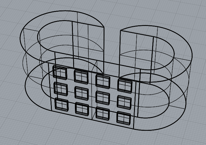
The design process utilizes variable sliders to determine the thickness and the length of the table. Python code is utilized when creating the multiple cup holder indents in the table. As before, the Rhino 8 Grasshopper code is uploaded to my GitHub page, with the name “M3_generative_table_noise”.
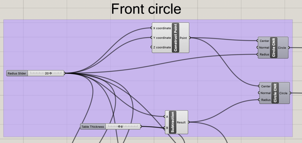
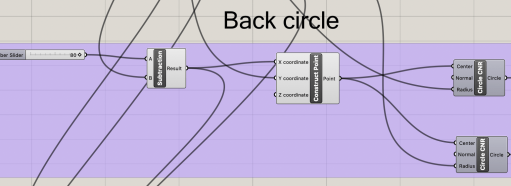
Creating the Circles
Both the front and back circles are the same size and with a smaller circle on the inside to act as a cutting circle to give the table internal space. A parametric slider is used to space the two circles apart from the “legs” of the table when extruded.
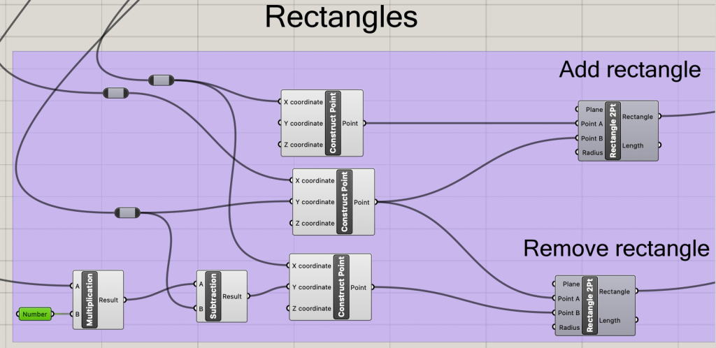
Cutting and Joining Rectangles
One rectangle is to join the two circle sets together, while the other one is to open up the internal space inside of the table. The of both of these rectangles is based off of where the centers of the two circles are in relation to the XY-axis.
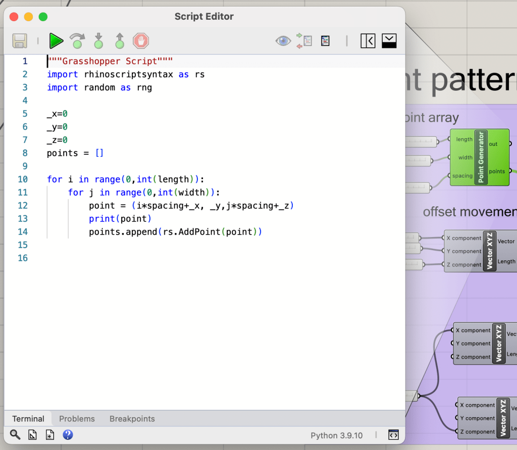
Cup holder Array
Through the use of two python grasshopper script nodes, a 2D array of points is created that can then be used to make a series of rectangles. I used this design opportunity to learn more about the available functions in the rhino-script library.
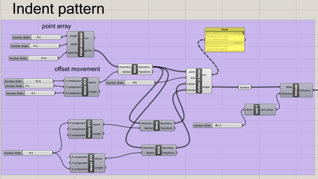
Through the input of a length and width the point array is created, and is then spaced accordingly by the parametric slider provided.
The rectangles are created by first creating a reference plane to place each rectangle upon. This plane requires correct
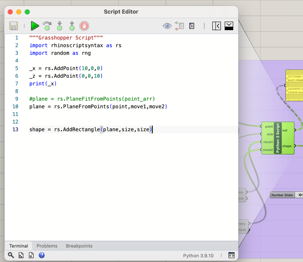
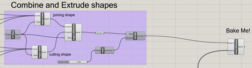
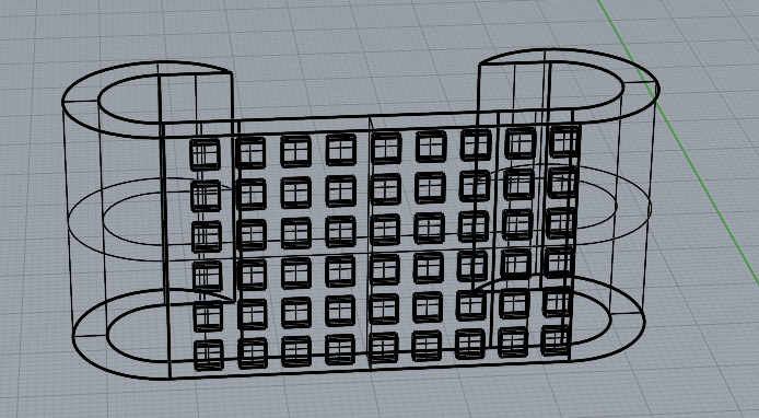
Forming the Shape and Extruding
The fitting shapes can now be combined and then extruded to the desired table width. Once the extrusion is done, the rectangle array can then be used to create indents using a solid difference node leading to the final table design.
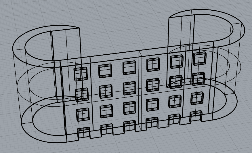
Some of the Created Tables


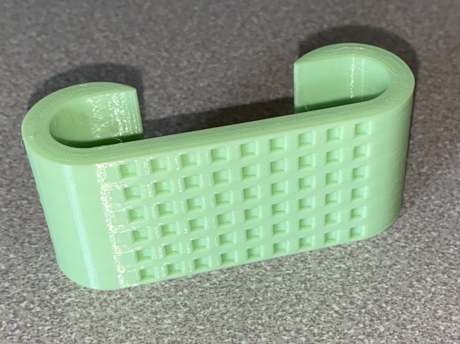
Task 2: 3D Fabriaction
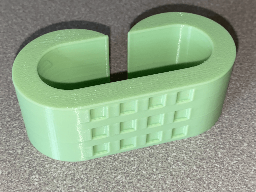
With the created STL files, they can then be placed into a slicing program (in may case the cure slicer) and then uploaded onto a 3D printer (My personal Anycubic Cobra Neo). The material used is PLA and each design took around 50 minutes to print at a 0.2mm layer height.
Comparison Between the STL and the Finished Prints

Conclusion
Much of the work done with 3D printing is done through the slicer. There are multiple difficult procedures done in the blink of an eye thanks to a slicer, such as supports or accounting for flow rate changes. With this brief excursion into 3D printing, the goal of making a rudimentary slicer is now more concrete as to why it is needed.

Leave a comment