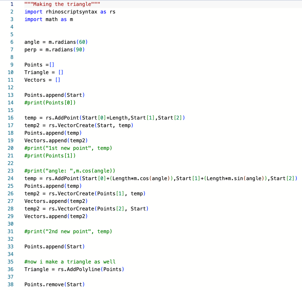
The final project in my computational fabrication class is a self-study project where a form of computation will be used to fabricate the design. In my case, I will be creating a print-in-place hinge based FDM printed fabric. As always, the codes on my GitHub, under the name “TriangleFabric” 1 & 2.
The Concept
Create a 3D printed system of hinges that will somewhat recreate how fabric flows and sags. I want to use a print in place locking system so that no assembly is needed for smaller scale tests, but can still be used for larger scale tests. To achieve this result, I will be using a hinge design to act as the joint of motion.
Many of the mehtods to create Fabric like 3D prints utalize either fabric directly, elastic materials or an overly intricate interlocking chain design. There are major issues with each of these current methods, the elastic materials and direct fabric printing require more fine tuning and specialized techinqies to print correcly, while the chain pattern can only really be used form one side due to the abrasive nature of the chain links.
The Process
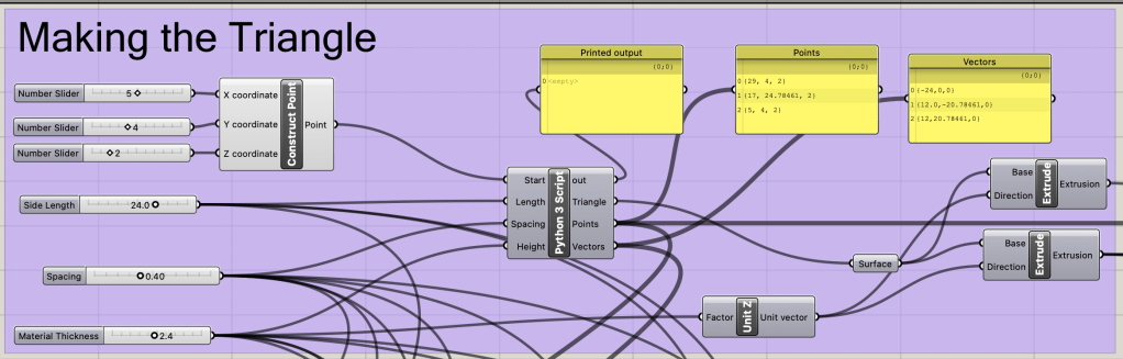
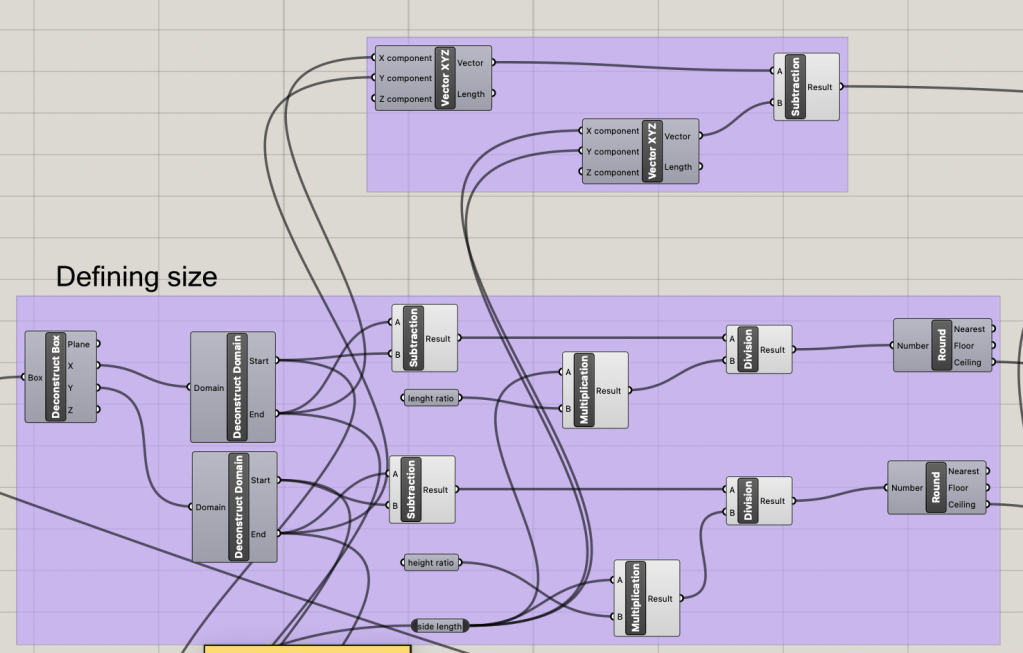
Creating the Base
The base of the triangle is determined by the input sliders of thickness and side length. The python script is used to determine the correct placement of the hinges and the correct direction for each hinge extrusion.
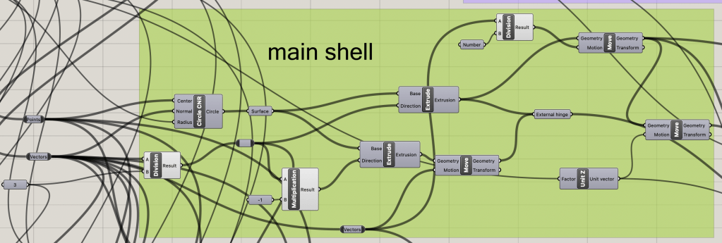
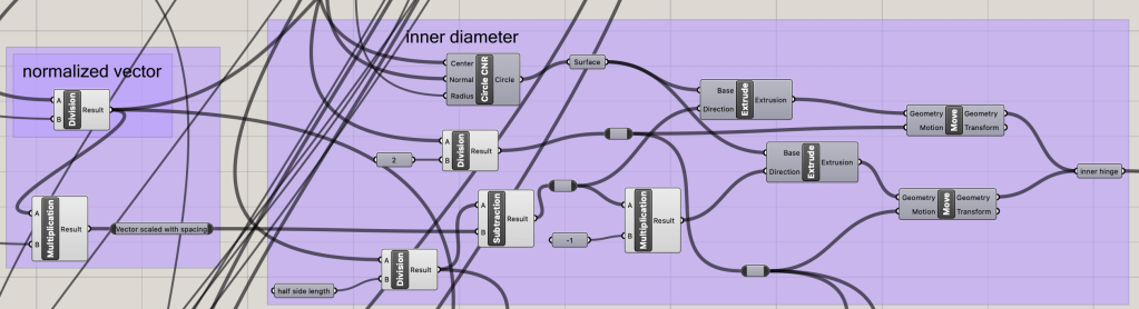
The Hinge Design
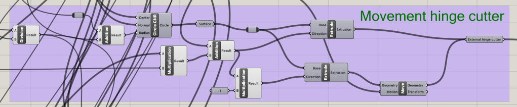
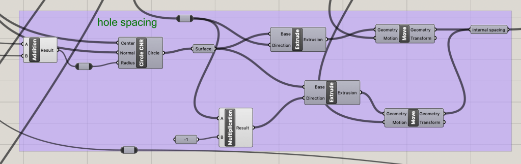
Though much of the design for the hinges is similar for each, there are slight differences to allow for a seamless fit when printed. Using the given points and vector direction as a base, the hinge parts can be spaced correctly when compared with the determined side length number. There are four cyliner needed to make the hinge: the external hinge base, the internal hinge base, themovement spacing and the hinge rod.
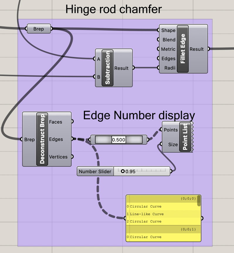
We then add a slight chamfer to the cutting cylinders and the hinge rod to allow for better printing and less deforming near the hinge.
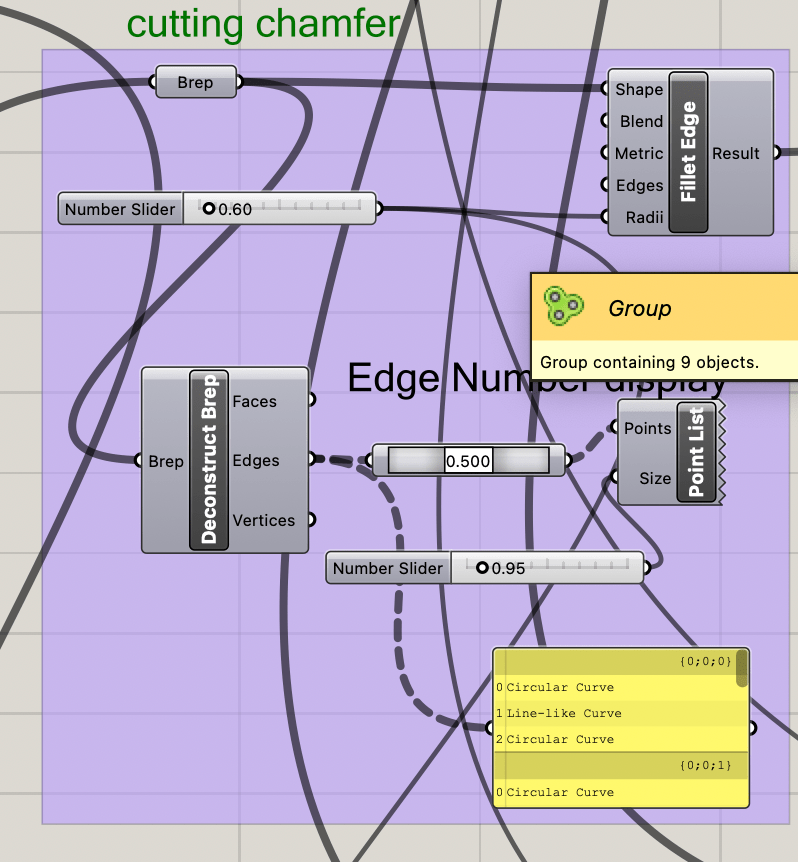
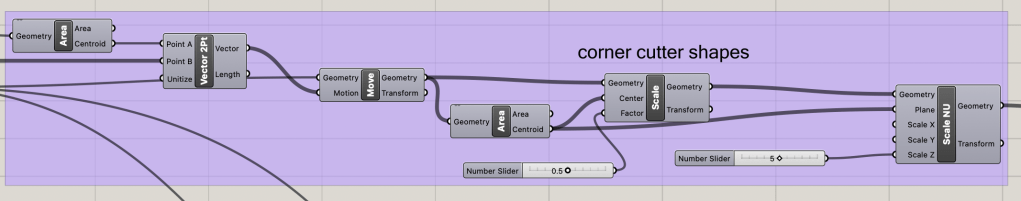
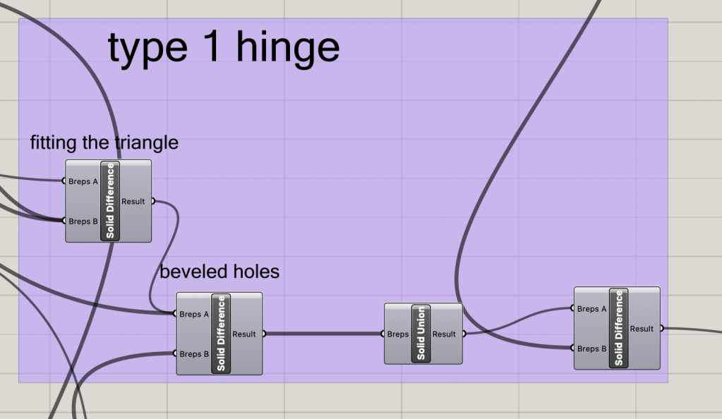
The hinge triangles need fit correctly, without overlapping sections, therefore some of the excess corners need to be cut so that nothing overlaps. This is done by making three cutting triangles that will be used after the main hinge section is formed to cut away the excess.
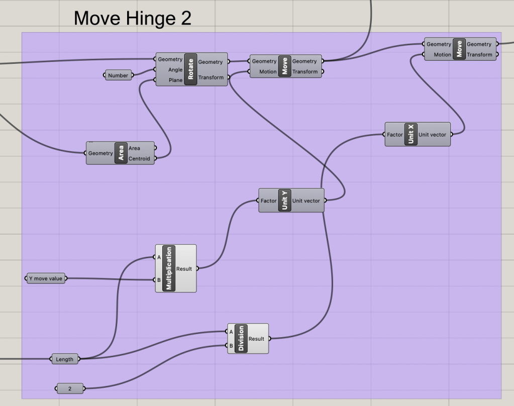
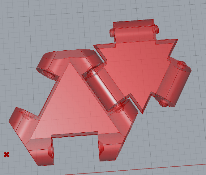
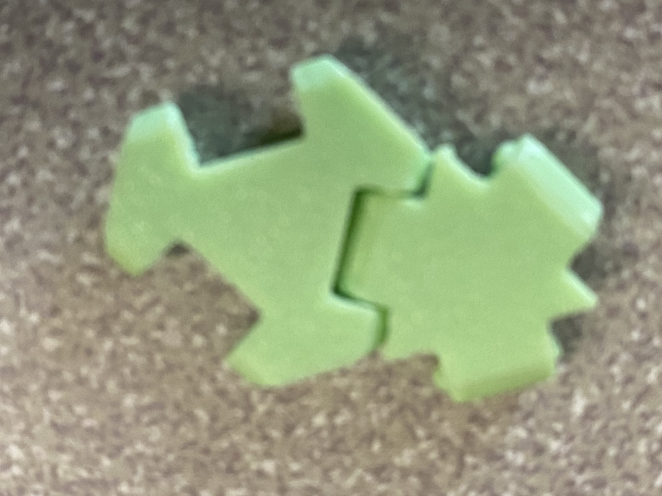
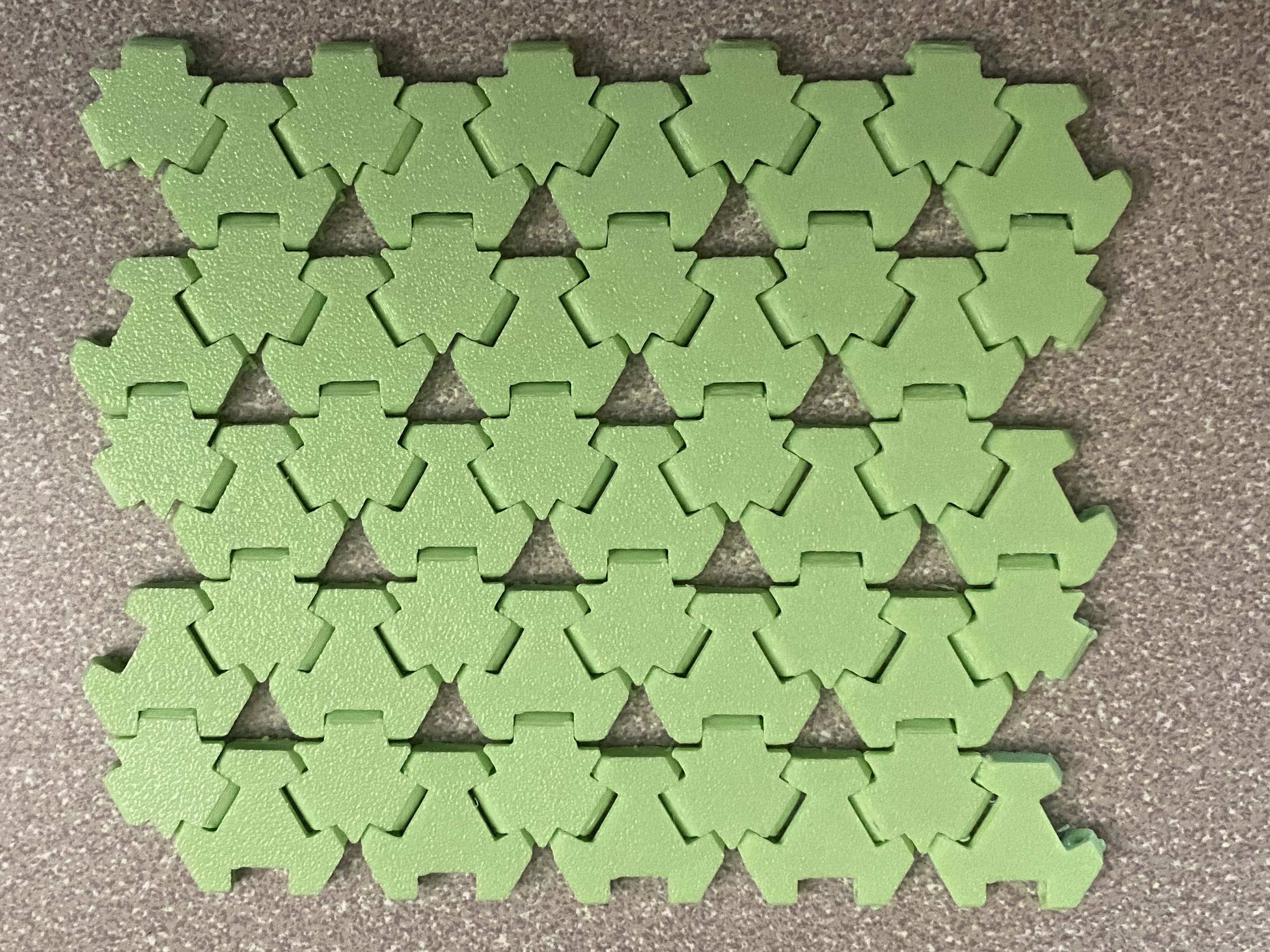
Now that all the pieces are together, the two hinge types can be created and then moved into the correct position to allow for a simple printing demo.
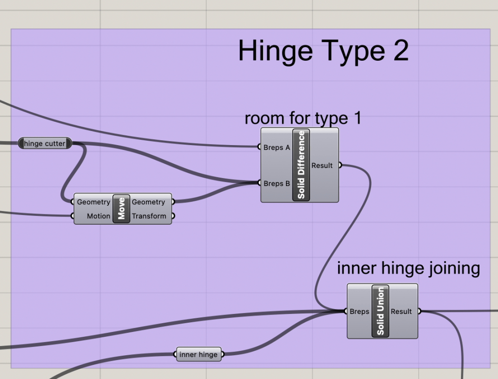
We can now work on joining the two hinges for a demo of how the system will work. Please note that used printer setting s were 0.12mm layer height, and most printers will ahve to instead have a larger spacing value in order to achieve similar effects.
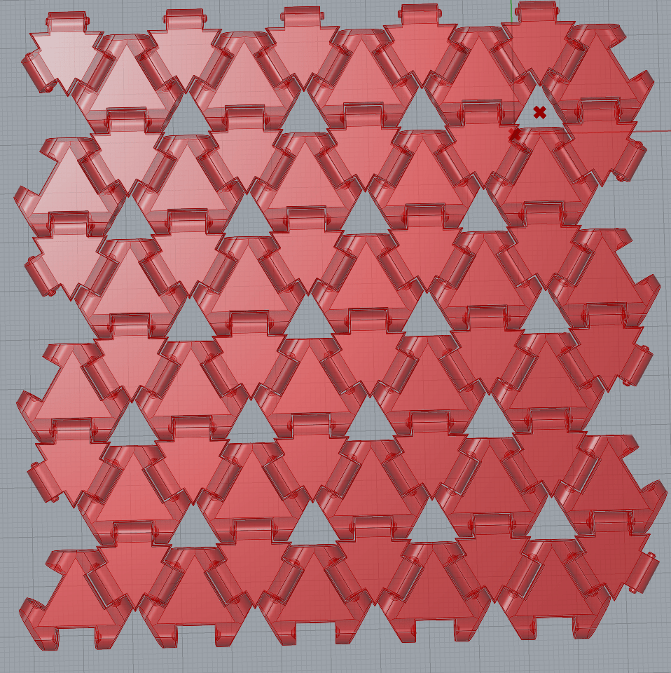
Making an array of Triangles
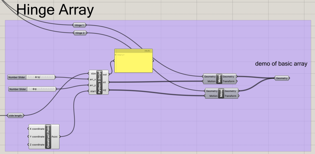
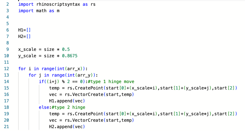
With a functional hinge, we can now make an array of the hinges without issue. To do this easily, we will use a python script again to correctly space all the hinge items and then populate them in a single array. To put the correct hinge item in each part of the array, we will use the concept of parity (if something is odd or even) to determine which hinge type will go where.
Fitting for an Input
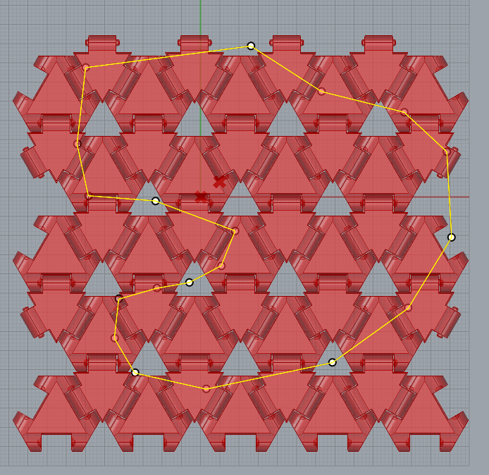
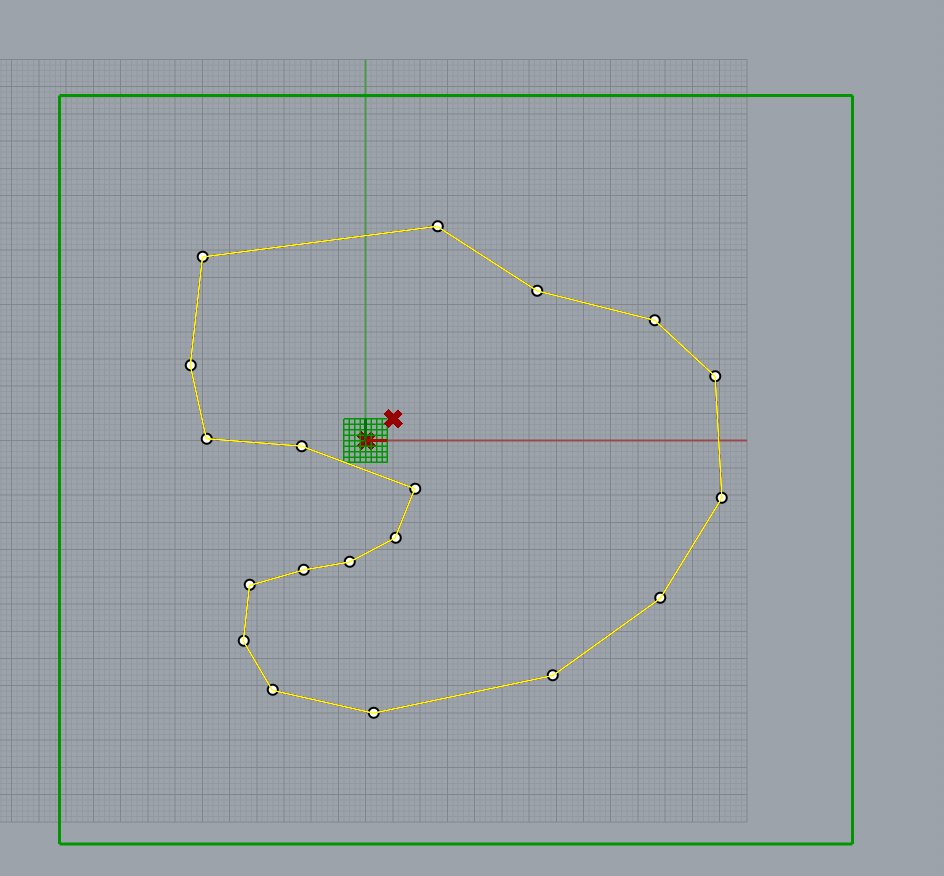
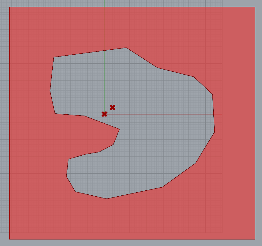
Making an array of hinges is all and good, but what if we wanted to make the array fit the hotline of a shape? Let’s first start with creating a shape in rhino and importing it to grasshopper. IN this case we will use a simple poly line.
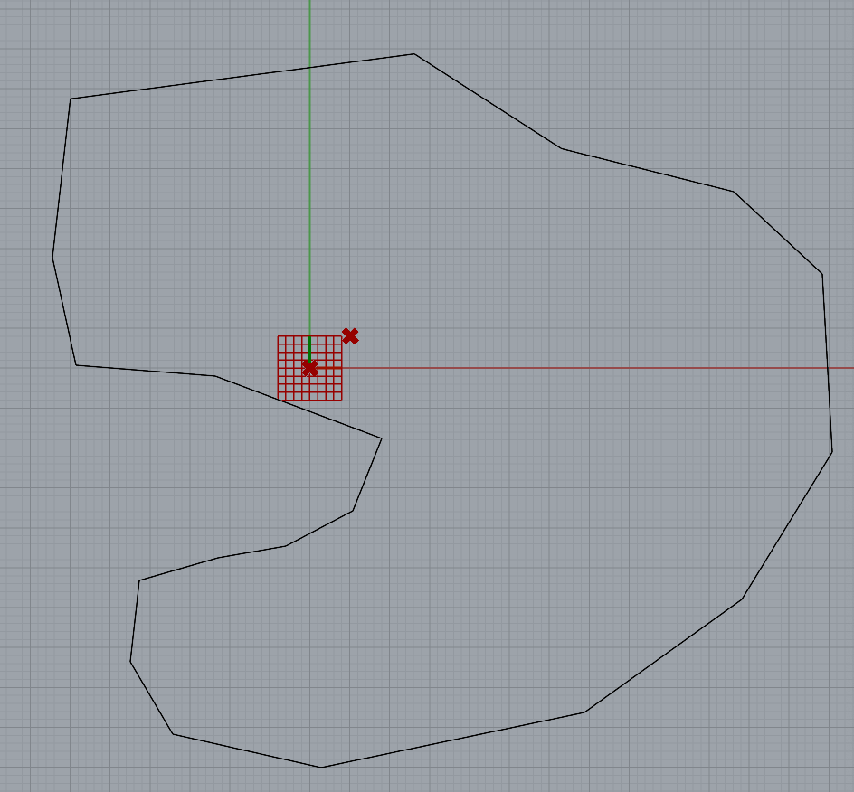
The next step is to create an array and bounding box that surrounds the input shape. We will skip over a few methods of creating the correct spacing and miving everything correctly, to first show the expected outputs of the shapes within the created bounds.
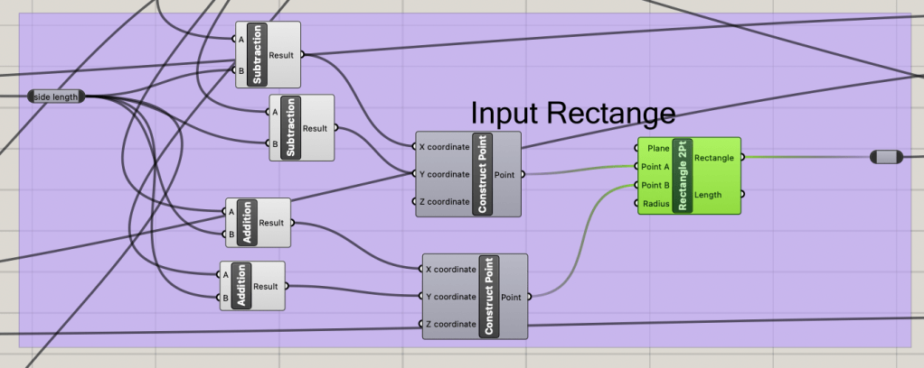
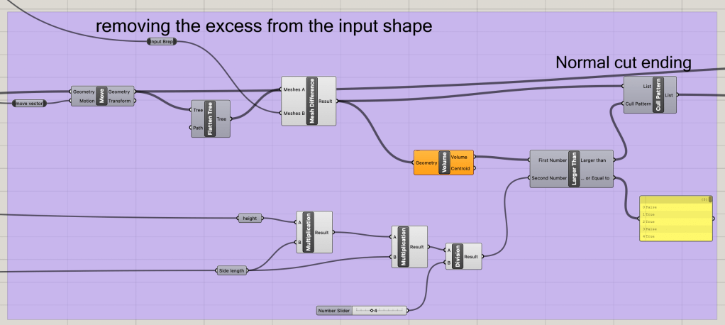
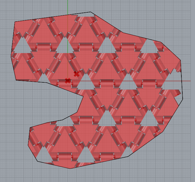
From the input shop and the created bounding box, we can create a cutting shape that will remove all the excess parts of the triangles that are outside of the lines of the shape.
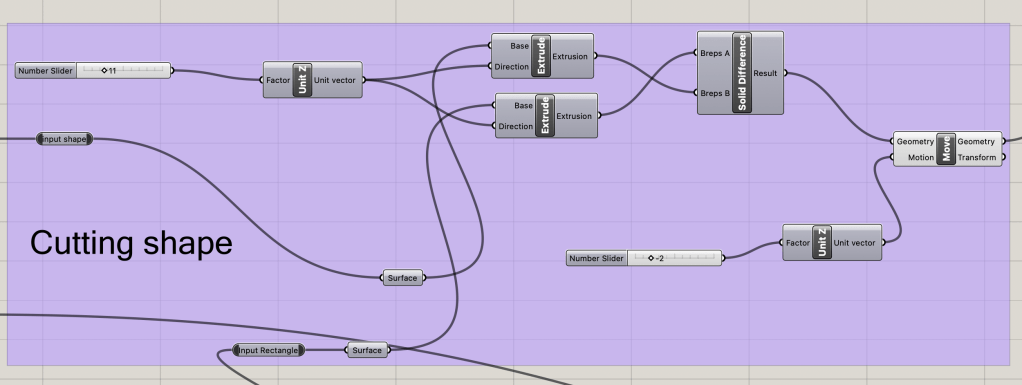
We can then take this cutting shape and create a mesh difference between the hinge array and cutting shape to leave a realistic imprint of the shape. The next step is to remove any minor part of the hinges that can’t really connect to anythign, or is too smal to actuall be there. This will. be done with a cull pattern and a volume comparison. Though this will make the hinges fit the shape slightly less, this would be a waste of material when the smaller parts fall off after being removed from the print bed.
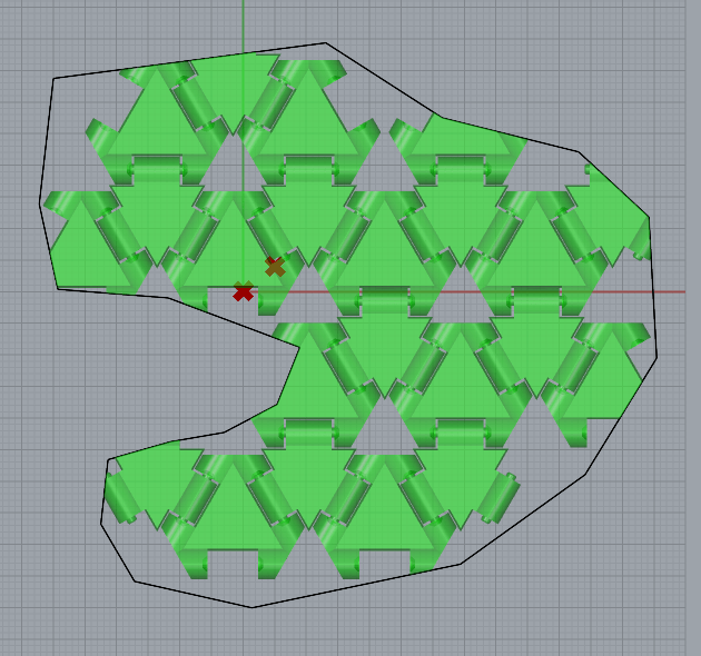
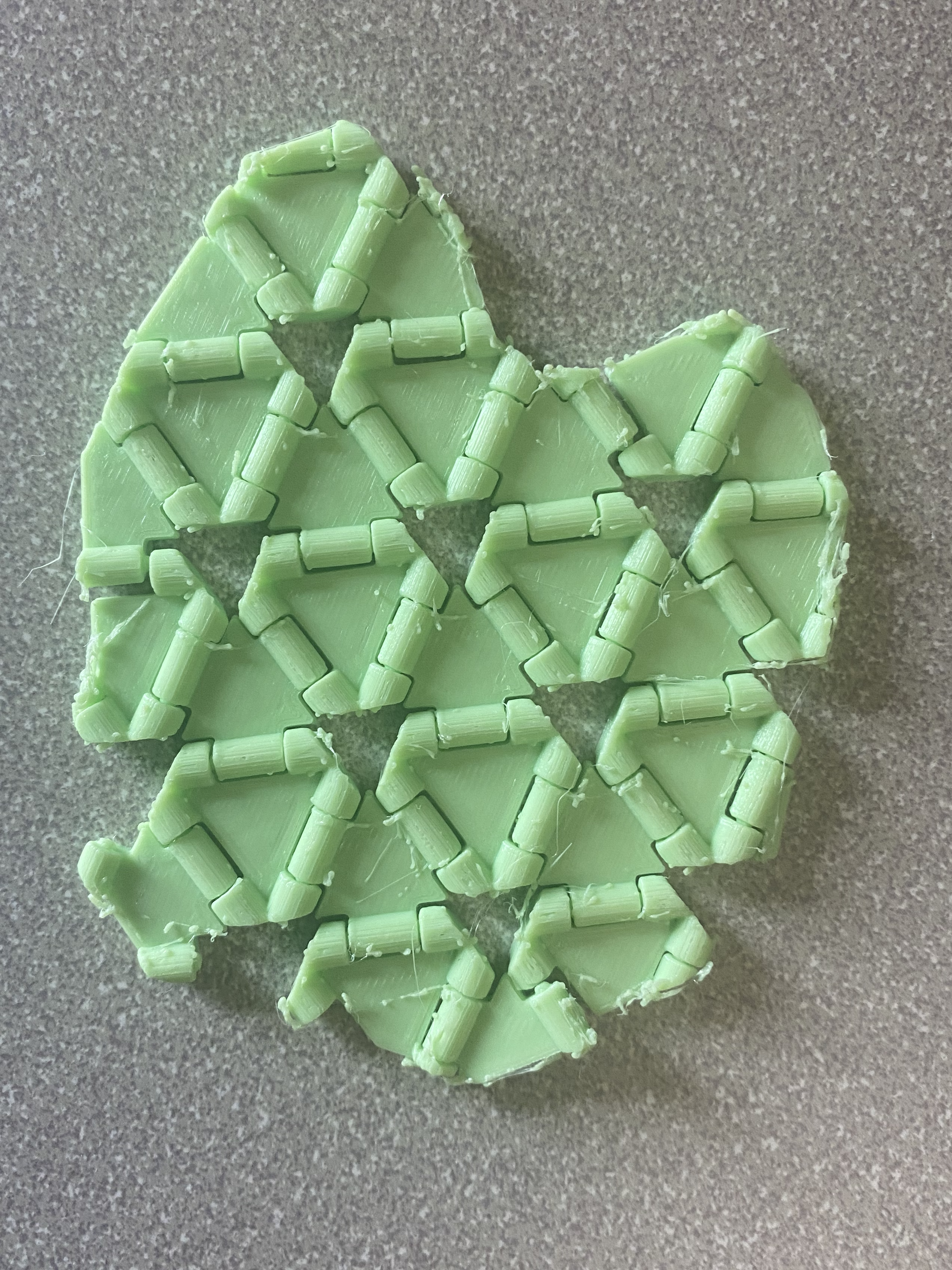
We can now export this design and print it as a single STL to allow for print in place. This setup can also be used to print circular cuts in the hinge array as can be seen in this printed demo of the hinges.
Conclusion
Using python simple geometry and planning ahead allows for most geometries to be created in rhino. There are just many auxiliary steps needed. My major complaint with the grasshopper system is how some data is formatted. All the hinges were in a pseudo list that I could not manipulate easily. This may be due to how external data from python is formatted in Grasshopper, but most four posts I read had similar issues with no really easy way to condense and consolidate.
I have greatly enjoyed this class and the formatting of both the assignments and the lectures. I have developed more skills and concepts for computational design. We’ll see what I try and make over the summer break with my newfound knowledge.

Leave a comment